It has been a month of expectation and waiting.
Waiting for the vaccine to be available for COVID. Waiting for the vaccines to catch hold nationally so life can start to return to normal. Waiting for some HR changes at work to take effect. Waiting for (hopefully good!) feedback on several model railroad media fronts. Waiting for the book to arrive for sale. All of these things should be great when they come to be, but as my favorite musical artist sings: "The Waiting is the hardest part."
And so, as a place to ground out the energy and the angst in the waiting, I have continued to pour efforts into completing the deep staging installation, with a goal of having it operational by April 1. It has taken each minute I have given it, and asked for more: this is without question the most difficult construction I have tried on this layout.
We left off last time laying track for the tangent. That task was completed shortly after the last post while the tangent stretch was still on the floor of the space, allowing for track to be aligned where I could see it without having to guess.
Once the track cured, I installed all feeder wires, also here on the ground. You can see the gentle bend in the middle of the tangents, required to deal with the challenging clearances once installed. I added re-railer sections, upper right above, just in case. The black steel brackets you can see in the upper left will support this installation, which needs to be close to the aisle at the left side to avoid the diagonal supports ahead to the right. But, immediately past that, the roadbed will need to curve towards the wall to the left and begin the climb up to the Island level.
Many thanks to Tom S. and Ralph H. for coming over to lift, shift, and slide this assembly into place! We made the big lift - and it went just about perfectly. Thanks to measuring three times, cutting once, and the foresight to assemble this piece on the floor, we were in good shape.
The alignment was exactly what we needed. Clearances all checked out. I however left it loose on the brackets pending the installation of the curved section - since the curve will be the link to the existing layout, it must be finalized first. Now it was time to tackle the curved section installation.
I had been thinking the curve design and install over for months, debating the approach with myself and with Scott S., a fellow civil engineer. Like the tangent section, there was no way to lay track once the roadbed was installed just 10" below the top section. Worse, the tight curves required here (20" radius in places!) made precise installation critical. The trackwork needs to be perfect at all joints and respecting all clearances for trains to handle this - there is no room for error.
The new curved benchwork too would be too long and large to be slid in from the aisle or floor. It didn't clear the adjacent parts of the layout.
The only choice left was to paint the wood ahead of time, add the guardrails ahead of time, then assemble the curved plywood in two pieces, after which track could be laid - all while the assembly was temporarily supported out from under the top level. But the only place to do that was on top of the uneven mainline ramps behind Iroquois: it is the only place I could fit the assembly where it could then be rotated into position. Putting heavy plywood over HO scale mainline track is always tough to stomach. And then, after all that, the whole thing would need to be rotated counter-clockwise over the Island tracks, along its permanent path slid between existing Island tracks and the layer above, before being set down onto the supports.
Ugh. Lots of room for mistakes and collateral damage. BUT - a clear path forward, and frankly the only possible one.
Even the clear path forward had its struggles. Here I am in one of my 'layout yoga' positions, on a ladder on an angle bent over mainline with my head against the ceiling, laying track that had to be exact. Not fun.
As the track cured, I double checked clearances again, even taking several of my longest locomotives and pushing them around the curve to ensure they cleared the sides and each other while on adjacent tracks. It was tight - but it worked! I weighted the track as seen above, a view where you can see the test engines too.
Once the track cured up, it was time to install 36 different feeders, ensuring that each piece of rail has its own hard-wire connection.
I continue to stand by my claim that resistance soldering, the technique shown above, is a clearly superior way to solder wires to rails. I was done with all that in one evening with only one melted tie to speak of. Not bad, and at least I could do it standing up!
After 5 long nights of late and hard work on this, now we can see the results - and I think it paid off. Here's the smooth curves of track using Atlas curved switches to save space. With all that work done, I cleaned up my tools and equipment, thought through the issues one more time, and took the plunge!
With a few bumps and strains, and a sudden satisfying THUMP, the curve slid into its spot. I had to carefully then adjust it so the extra track from the tangent piece ended up above the curved end. I fastened the curve in place with risers as seen above, then made the adjustments to ensure the tangent piece lined up, which was then too fastened in place. I had left 16" long tails of flex track in place on purpose on the tangent to smooth the joints, and those needed to be trimmed to fit exactly over the transition.
With some careful measuring and lots of time, I trimmed the track using a Dremel tool since the big code 100 rail had destroyed my rail nippers. The backup plan worked great, though. The track slid into place. I spread adhesive below the loose area, then slid joiners into place and laid the track. The result was better than I had expected, shown above. Yes the track is old used Atlas Code 100 flex - ugly stuff by today's fine standards - but robust and cheap and therefore perfect for hidden staging areas!
The final step was the final joint between the curve and the Island staging subroadbed, which I did with steel strips for extra rigidity at this odd joint. With both routes descending, there is a lot of torsion on these bars, but they are more than up to the task.
So while the waiting takes so long and so much energy, it is being great to have this project to plow along through. Next time we will look at final cut-in of the yard to the existing track, and the installation of Tortoise machines and controls. Never a dull moment on the Onondaga Cutoff!


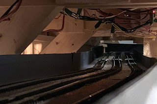




 This image shows a typical installation for a pair of the Circuitron 'Tortoise' machines. These come with a mounting jig, allowing the installer to locate the machines using a small hole drilled through the benchwork at the location of the throwbar on the turnout. Four pilot holes are drilled for mounting screws, and the machine is installed from below the subroadbed. I had to check the alignment several times in order to get the location just right, but it has worked out well so far.
 This is the 'heart' of one of my interlockings, CP 295. This is the 'west' end of my staging yard, and this terminal strip is how I have routed a separate power suppy to the switch machines. While I used red and white wire for track power, I have used black and green for switch power, and will someday use blue and yellow for signal power. The heavier 14-gauge green and black wires lead to another terminal strip which is the location from which all my switches will be powered, and it in turn is wired to an old transformer set to 10 volts.

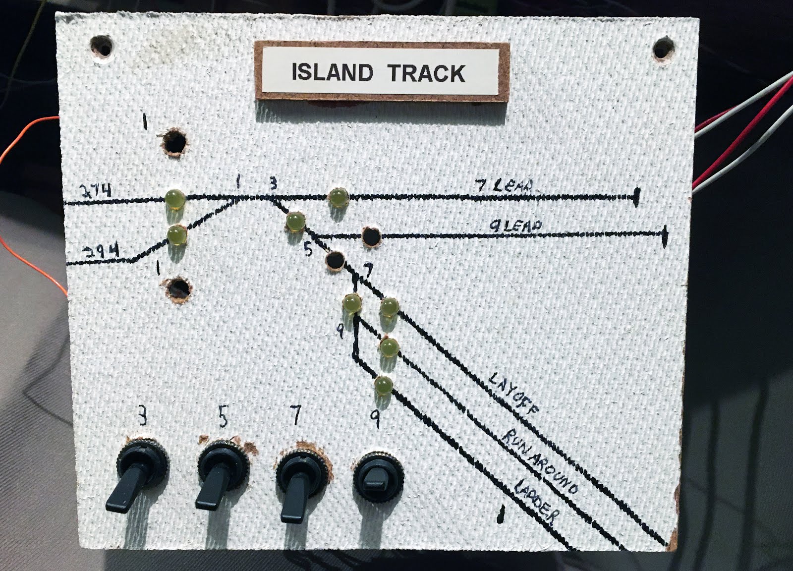
 The temporary model boards for each end of the staging yard...
  And, finally, a close-up shot showing the throwbar itself on a Micro-Engineering #6 switch in the staging yard. If you look at the close end of the throwbar, you can just barely make out the end of the steel wire that links the machine to the throwbar and moves the point rails. It's a nice set-up and worth the extra money compared to other machines.